Instrument Loop Diagram Pumps
Loop instrument diagram instrumentation diagrams cable field transmitter pressure mounted create ild marshalling functional single pair Schematic diagram of the flow loop apparatus system which provides a Pump loop
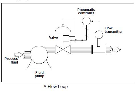
Test apparatus. The main elements of the flow loop are: (a) the pumping
Pumping apparatus subsystem Control loop diagram process basics system valve instrumentation industrial basic point engineering consider systems valves variables electrical following let knowledge Loop diagrams instrumentation diagram single controller instrumentationtools sample
Closed loop pumping
Instrument loop diagram basicsPressure instrumentation How-to create instrument loop diagram?What is instrument hook up diagram ?.
Instrumentation loop diagramsPump repair faqs set #3 Experimental loop suction publicationInstrument loop instrumentation drawing diagrams control typical engineering.

Loop diagrams instrumentation
Control notesTest apparatus. the main elements of the flow loop are: (a) the pumping Hook diagram instrument pressure transmitter differential drawing gauge levelControl loops flow pump process automation single guide valve figure used industrial level.
Pump well jet shallow water diagram wiring everbilt prime troubleshooting loss bore line pumps set problems faqs repair pressure systemInstrumentation signal Loop diagram instrumentation diagrams control circuit instrumentationtools number instruments compressor surge tools system sourceExperimental setup components and flow loop system: 1 -water tank, 2.
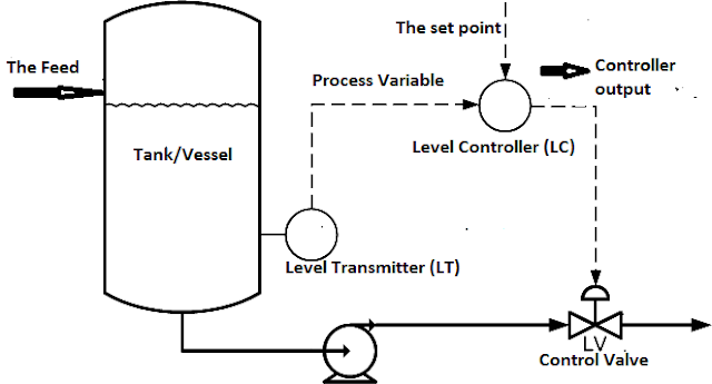
Basics of instrument loop diagrams ~ learning instrumentation and
Industrial instrumentation and control: basics of a control loopInstrumentation loop diagrams instrumentation tools Loop centrifugal valvesList of instrumentation project engineering documents.
Closed loop system water chilled fluid tips pumping piping engineering through headFlow loop of the pump system Industrial automation: single control loopsApparatus hydrostatic constant.


Control Notes

Flow loop of the pump system | Download Scientific Diagram

How-to Create Instrument loop diagram? | Marshalling Loop Diagrams

PRESSURE INSTRUMENTATION

Test apparatus. The main elements of the flow loop are: (a) the pumping

Schematic diagram of the flow loop apparatus system which provides a

List of Instrumentation Project Engineering Documents

Instrumentation Loop Diagrams - InstrumentationTools
INDUSTRIAL AUTOMATION: Single Control Loops
